Custom customer solutions
From an evening chat to having a custom product in your hand the following day. The kind of thing formula 1 teams strive for can be achieved in just a few focused hours.
This is a long read following the process of a custom build for a customer.
With people at home more than usual of late, we all find ourselves procrastinating and tackling all of those big projects we have sat around our workshops.
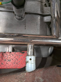
 One such task was Andy Green's (of Racing Green) Aermacchi which he is building up to compete in classic motorcycle racing. Among many other things discussed; the side fairing brackets needed looking into. The existing nylon ones he has fitted were profiled to an old fairing and appeared to have been held on by string through the drill hole and the fairing attached by an M6 bolt threaded into the nylon. Functional but we could do better.
Design requirements
Cutting or drilling the frame was out of the question ruling out any bolted or split pinned attaching devices.The fairing bung would need to attach to the frame and allow a bolt to attach it to the fairing. It will attach on a flat surface and should have a broad end to spread any loads on the fairing should it take a knock. It will need to cope with both heat and vibration whilst remaining light and quick to remove, preferably without undoing the bolt.
I took some measurements and went home to mull the design over.
I had some ideas of using a fork and locking collar or maybe an cammed resistance locking mechanism but all of these things added complication and would be at risk of coming undone due to vibration. The key was simplicity but that doesn't mean it has to look unsightly.
 The design I settled on wasn't light years away from what it was replacing.
 The body design consisted of a bung that would sit in the fairing tube with a rounded end and a clearance fit to make fitting and removal easier. The main body is of the same diameter as the fairing tube for a consistent look before flaring out to meet the fairing in the load distributing manner required. the flared end was also bevelled to reduce edge damage.
 Fixtures were provided by an M6 nut which would be captive in a blind interference fit slot and another slot provided for a tie wrap allowing the bung to be secured to the frame.
The design was drawn and rendered in Fusion 360. This was then exported as an .STL file which I sliced using Cura for its first test print in PLA on the Copymaster 300.
These came out well. The design lending itself well to 3D printing with minimal overhangs that the printer coped with nicely.
Immediately I identified the printer had over extruded causing tolerances to tighten up on the slots and holes. This wouldn't be a problem for a proof of concept so I cleaned them up and headed over to Racing Green that evening to test fit the first draft of the fairing bung.

The test fit was a success. We selected a tie wrap that would best suit Andy's needs then it was back home to adjust the design accordingly.
I increased the nut and tie wrap clearance, added a bevel to the non locking side of the tie wrap hole for a smoother curve. The logo was changed to the correct HPE design (took me a while to notice that mistake!) and also curved the embossed logo to follow the curvature of the bungs body. This now more tidy looking logo is on one side only to further clean up the look.
 This time the design was printed in the final PETg filament which is heat resistant and strong whilst maintaining some ductility to cope well with vibration.
A quick review later and I was happy that the final design had come out right. A couple of sets were then batch printed and had them in Andys hand (still socially distancing mind) the following evening. From initial request to final product in two evenings. Not too shabby.


Comments
Post a Comment